Pollution monitoring
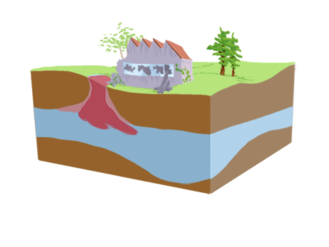
The location and temporal extension of soil pollution is of paramount importance for land-use planning, agriculture, water resources and soil depollution. According to the type of pollution, electrical resistivity or induced polarization can be linked to the presence of pollutants.
The Syscal and Syscal Switch range will allow to locate, determine the spatial extension and monitor such pollutions (Syscal Kid / Syscal Kid Switch / Syscal Junior / Syscal Junior Switch / Syscal R1 / Syscal R1 Switch / Syscal R2 / Syscal Pro / Syscal Pro Switch).
For large areas, the pollution extension can be determined more easily and rapidly using the Promis 10 slingram type EM profiler to realize resistivity maps.
Waste disposal

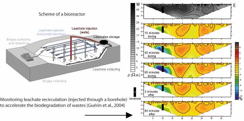
Waste disposal are objects that need to remain under supervision during their whole lifetime. The first aspect of this supervision consists in checking the proper containment of wastes to avoid leachate’s leak through the geomembrane and through the possible clayey layers. The second aspect deals with the monitoring of the homogeneous re-circulation of leachate in the waste disposal to ensure an optimal biodegradation of waste.
The Syscal Switch range will allow to locate, determine the spatial extension and monitor the proper functioning of a waste disposal site (Syscal Junior Switch / Syscal R1 Switch / Syscal Pro Switch).
In the following example taken from Guérin et al. (2004), the leachate of a bioreactor is pumped and re-injected through a borehole. A monitoring of the electrical resistivity allows to image the recirculation of the leachate (expansion, velocity, diffusion). This type of measurement can be realized with a Syscal Pro Switch in monitoring mode to optimize the number and location of boreholes used for the reinjection of the leachate.

Buried structure
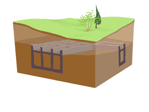
During archeological studies, the determination of the location and of the spatial extension of the buried structures (e.g. walls of ancient and existing buildings, Himi et al., 2016) allows to determine precisely the area of investigation and the geometry of the buried structure (Selim et al., 2014, Terron et al., 2015). Electrical resistivity has been shown useful to image remains of buildings, tombs and other traces of ancient human activity.
The Syscal range is well adapted to image such structures at shallow depth (Syscal Kid Switch, Syscal Junior Switch). The following example shows the ability of the Electrical Resistivity Tomography (ERT) to image a tomb at shallow depth (0.5 - 1m) with a Syscal Kid Switch.
References
Guérin, R., Munoz, M. L., Aran, C., Laperrelle, C., Hidra, M., Drouart, E., & Grellier, S. (2004). Leachate recirculation: moisture content assessment by means of a geophysical technique. Waste Management, 24(8), 785-794.
Himi, M., Pérez-Gracia, V., Casas, A., Caselles, O., Clapés, J., & Rivero, L. (2016). Non-destructive geophysical characterization of cultural heritage buildings: applications at Spanish cathedrals. First Break, 34(8), 93-101.
Selim, E. I., Basheer, A. A., Elqady, G., & Hafez, M. A. (2014). Shallow Seismic Refraction, Two-Dimensional Electrical Resistivity Imaging, and Ground Penetrating Radar for Imaging the Ancient Monuments at the Western Shore of Old Luxor City, Egypt. Archaeological Discovery, 2014.
Terrón, J. M., Mayoral, V., Salgado, J. Á., Galea, F. A., Pérez, V. H., Odriozola, C., ... & Pizzo, A. (2015). Use of Soil Apparent Electrical Resistivity Contact Sensors for the Extensive Study of Archaeological Sites. Archaeological Prospection, 22(4), 269-281.


