IRIS Instruments
HomeLogin

Mineral exploration

Detect dyke

Detect dike

For mining exploration applications, the method and equipment to use depend on how the precious metal is concentrated or disseminated in rocks, on the size of the orebody but also on its depth. When precious metal is concentrated in a dyke, the detection may be performed by resistivity profiling using the Promis 10 Slingram type EM profiler or the T-VLF to image resistivity or the Syscal range equipment to measure electrical resistivity or induced polarization (Syscal R1 / Syscal R2 / Syscal Pro).
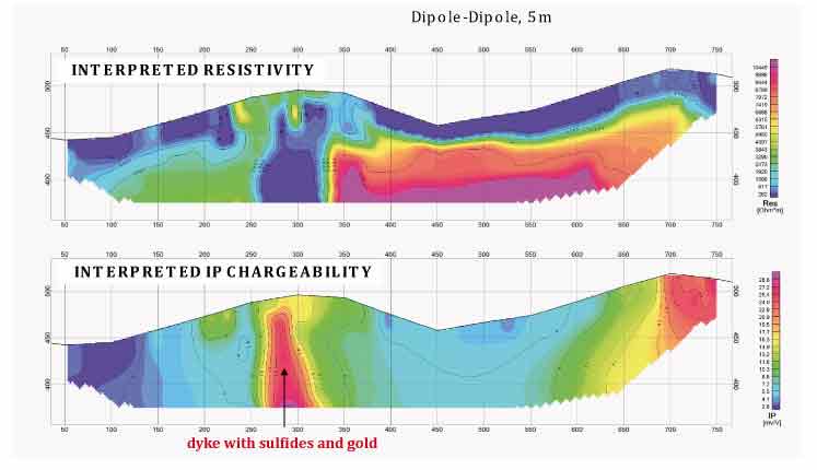
The following example shows how a sub-vertical dyke can be detected both with electrical resistivity and induced polarization. It has been acquired in Brazil using a Syscal Pro 48 with a 20m spacing dipole-dipole sequence. The electrical resistivity can only indicate the presence of a dyke.  The associated anomaly can be conductive when filled with clayey material or highly resistive when containing quartz inclusions . The induced polarization (computed here as chargeability) is able to give an information on the content of sulfide (even disseminated) in the dyke, and therefore the possible presence of gold or other researched minerals.

Locate fault or dike


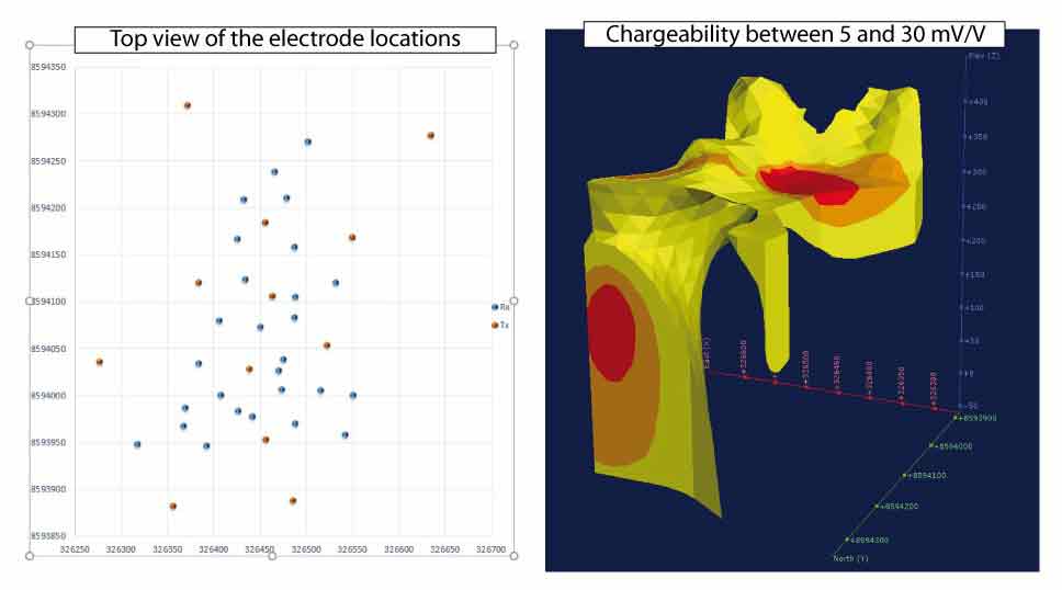
For deep application and induced polarization measurement, we recommend the use of separate transmitter and receiver by using the TIPIX or VIP transmitter ranges associated to the Elrec of Fullwaver ranges of receiver. This method allows for sounding, profiling and imaging electrical resistivity and chargeability of the soil.

Deep orebody

Deep orebody

For mining exploration applications, the method and equipment to use depend on how the precious metal is concentrated or disseminated in rocks, on the size of the orebody but also on its depth. The deep orebodies are generally difficult to image with geophysics and can require large 2D/3D tomography to estimate volumes. The VIP range of transmitters combined with the I & V Fullwaver equipment are dedicated to this type of applications. The setup of several tens of static V Fullwavers (cableless) combined with the I Fullwaver that measure and store the current injected by the VIP transmitter at different location on the survey area, allow to measure, store, process and easily extract a 3D model of electrical resistivity and induced polarization.
Hereafter is presented a rapid example realized with 9 V-Fullwavers and one I-Fullwaver. 27 static measurement electrodes (blue points on the picture) have been setup on the area of investigation and 12 current injections (red points on the picture) randomly located have been performed using a pole-dipole array. 12 hectares have been covered on a mountaineous area (200 m max. of vertical drop). The automated post-processing allows to create a 3D image of the area in a record time (see 3D image of chargeability).

Locate fault or dike


A work in 2D or 3D is also possible using the Elrec Pro receiver associated with the switch Pro boxes and cables.

Lens type orebody

Lens type orebody

For mining exploration applications, the method and equipment to use depend on how the precious metal is concentrated or disseminated in rocks, on the size of the orebody but also on its depth. Depending on its depth, lens type orebody can be detected by 2D or 3D tomography which is completed with TIPIX or VIP range transmitters associated with the Elrec range receivers.
For large and deep lens type orebody, the setup of several tens of static V Fullwavers (cableless) combined with the I Fullwaver that measure and store the current injected by the VIP transmitter, allow to measure, store, process and easily extract a 3D model of electrical resistivity and induced polarization.

Documentation

Resistivity & IP
Step-by-step operation of SYSCAL resistivitymeters
pdf
Note on the depth of investigation of electrical methods
pdf
Multi-electrode resistivity imaging for environmental and mining applications
pdf
pdf
General safety instructions
Introduction guide to 3D resistivity imaging
pdf
Induced polarization current waveform
pdf
Introduction guide to 3D resistivity imaging
pdf
Step-by-step operation of VIP transmitters and ELREC receivers
pdf
Multi-electrode and multi-channel receivers
pdf
How to draw the maximun current from a transmitter
pdf

Contact us

Placeholder Picture

IRIS Instruments
1 avenue Buffon
45100 Orleans
France


Support:
+33 466-240-948
IRIS Instruments newsrss feedLinkedinfacebookTwitterGoogle +

Placeholder Picture

Lat: 47°49'39.69"N
Long : 1°56'12.49"E


IRIS Instruments
1 Av. Buffon 45100 Orléans, France
Copyright © IRIS Instruments. All Rights reserved.